Get a 3D scan
Get an instant price and order your scan today.


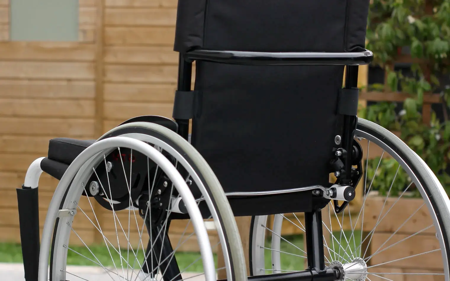
The wheelchair frame serves as the structural core, providing essential support for the user. Engineers design frames to be strong, lightweight, and versatile, carefully considering manoeuvrability to achieve optimum performance.
For this project, 3D scanning was used to capture competitor reference data, enabling a clearer understanding of the geometry, angles, and dimensions within the existing design. This information helped identify features that could be refined or enhanced. The scanned data was then reverse engineered to produce new bent tube profiles and manufacturing CAD models.
Capturing tubular frame geometry manually can be challenging and susceptible to human error. 3D scanning eliminates this issue by producing an accurate digital model of the frame and hinge assemblies, ready for analysis, reverse engineering, or inspection. In this case, the white-painted frame posed no difficulties for the scanner and resulted in precise, dependable data.
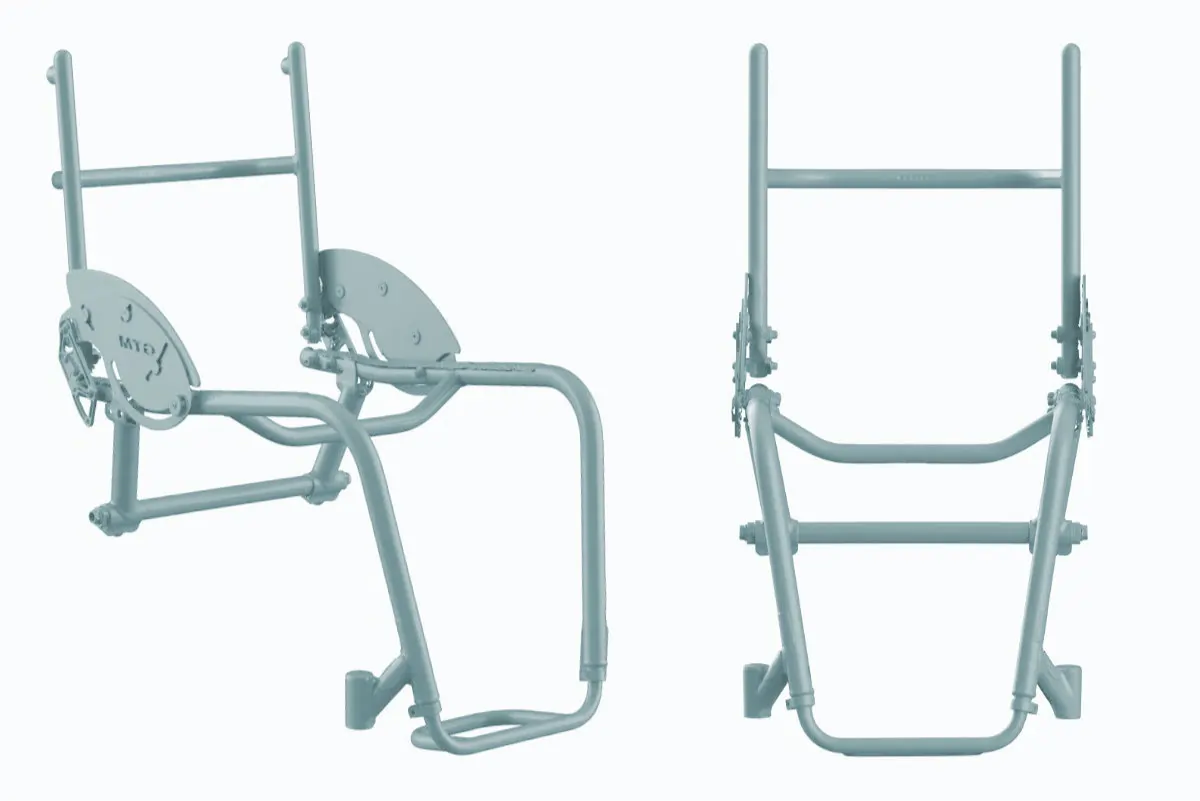
Base Wheelchair Frame 3D Scan
Next, we moved on to the competitor frame. This model was constructed from bare titanium and featured a fixed, non-folding design, making it notably different from the first frame.
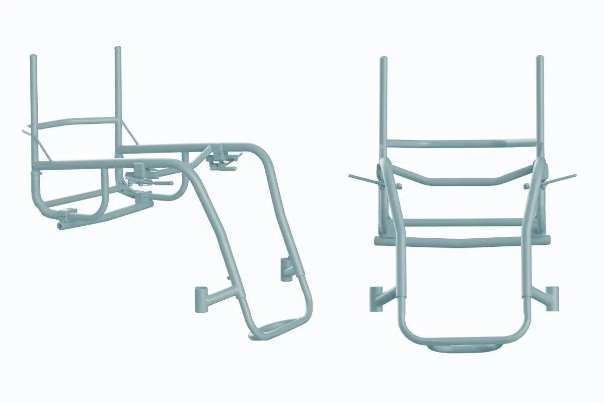
Competitor Wheelchair Frame 3D Scan
By overlaying the two 3D scans, the geometric differences between the frame designs become clear. This comparison enables designers to assess:
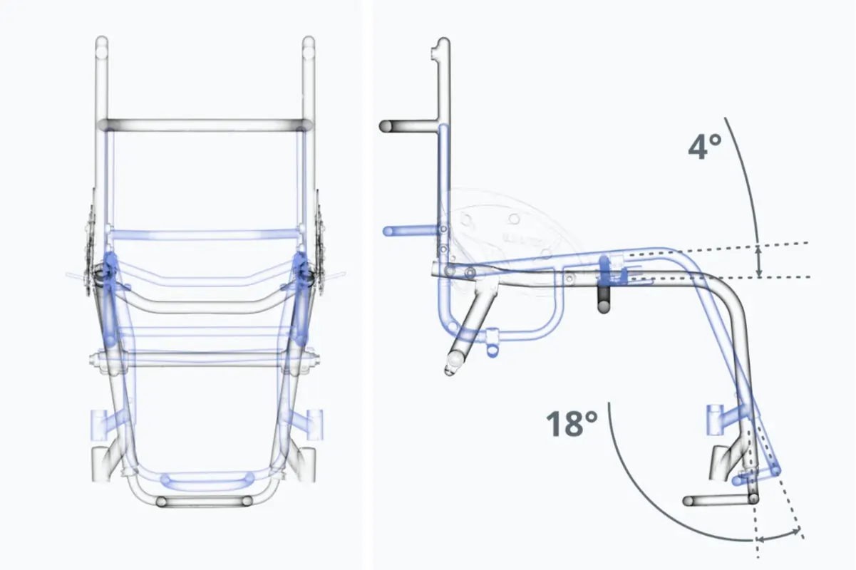
Importing the 3D scan data of the wheelchair frame into reverse engineering software enables the creation of an assembly made up of individual tube sections. These can then be cut, bent, and notched according to highly detailed and precise CAD data. This approach is ideal for reproducing legacy frame assemblies or producing a benchmark frame for comparative analysis.
Once the new parametric CAD data was finalised, a deviation analysis was carried out. With tolerances set, results showed that the majority of the model was within 0.5 mm of the original scan data.
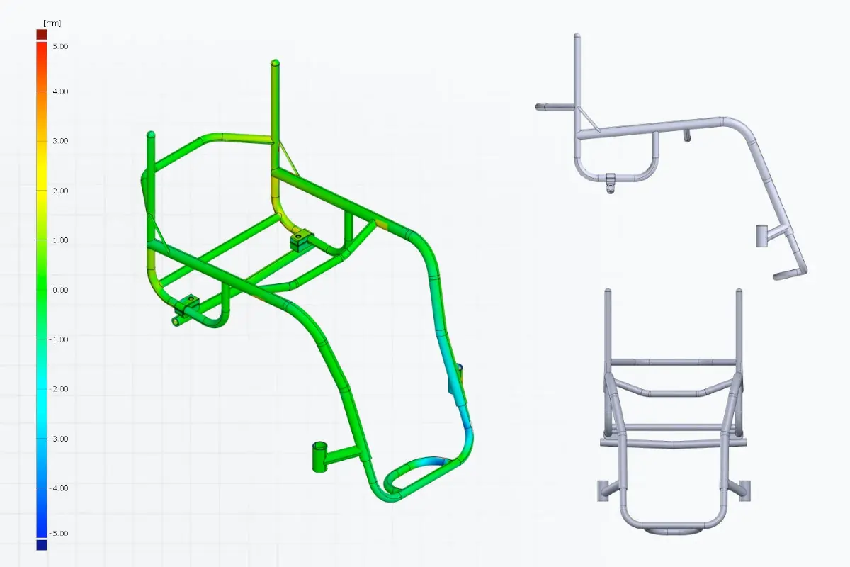
CAD-to-scan Deviation Analysis (left) & New CAD (right)
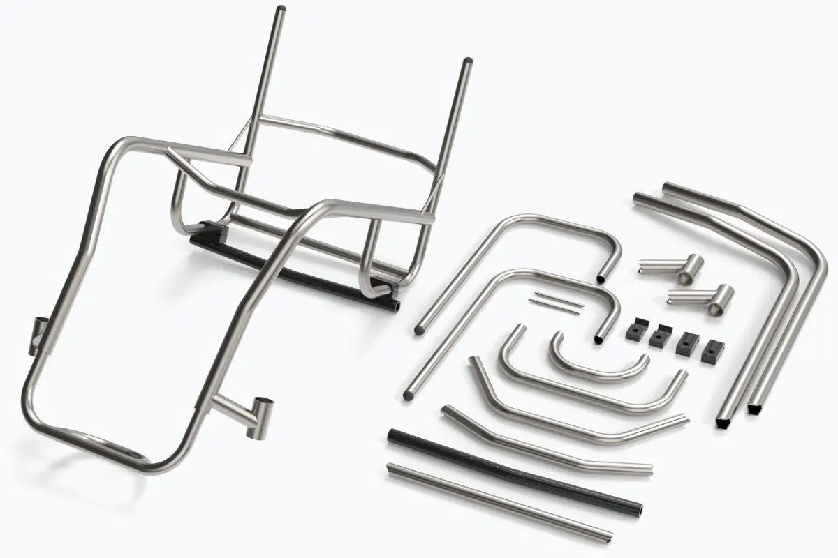
New CAD Ready For Manufacture