The 3D scanning knowldge hub

Frequently asked questions

3D scanning captures a part, model, or scene and converts it into precise digital data. The resulting scan matches the exact scale of the physical object, including all dimensions, surfaces, and features. This eliminates the need for time-consuming and resource-intensive manual measurements and feature-by-feature CAD modelling.

Transparent surfaces pose the greatest challenge for most 3D scanners. This is because the reflected light (whether white, laser, or infrared) becomes scattered, weakened, or fails to return to the scanner’s sensor altogether.

To overcome this, we can use specialised 3D scanning sprays that create an ideal temporary coating on the surface. These sprays evaporate naturally after a few hours and require no cleaning afterwards.

Note: Some scanners struggle with dark or reflective surfaces as well; however, our scanners do not. Therefore, the use of scanning sprays on these surface types is rarely necessary.

If the collected data is fully watertight, then yes.

There are several ways to achieve this, such as ensuring the entire part is scanned without any holes or by processing the model further during post-production. However, it’s important to note that any imperfections, including deformation, wear, or damage, will also appear in the print. We can address these issues if required, though this involves a more detailed and time-consuming process.

We are a studio-only 3D scanning service and not travellng to 3D scan on-site.

Our scanners can capture parts ranging in size from a snooker ball to a car. For items smaller or larger than this, we have the equipment, partners, and network to accommodate your specific requirements.

We can send your data in whichever way suits you best. If you have your own portal or FTP, we’re happy to use that — alternatively, a standard file transfer site works just as well. Unless otherwise specified, we’ll provide a WeTransfer link by default.

The whole point of 3D scanning is that it’s fast and efficient and we make sure it stays that way.

Urgent projects can be completed on the same day if required, while only larger or more complex projects typically take longer than a week.

This depends on the level of data you require. We can send .STL mesh files, .STEP/.IGES/.X_T model files and even native .PRT/.SLDPRT if we reverse engineer parts fully.
Key Knowledge

Quick, punchy and informative to support your understand of the world of 3D scanning and reverse engineering

1.0 3D Scanning vs. Reverse Engineering

It depends on the intended use of the data.

The captured data can either be used to produce reference information (3D Scanning) or to generate fully defined parametric CAD models (3D Scanning combined with Reverse Engineering).
3D Scanning (Reference Data)

– Can include colour
– Not editable
– Ideal as a spatial model for identifying clashes
– Provides surfaces to work from
– Suitable for measurement and inspection
– Can be used for FEA analysis
Reverse Engineering (Parametric CAD data)

– Editable CAD is created in native formats
– Improve design
– Reinstate design intent such as flat surfaces or worn edges
– Manufacture new parts from

2.0 Accuracy vs Resolution

Accuracy

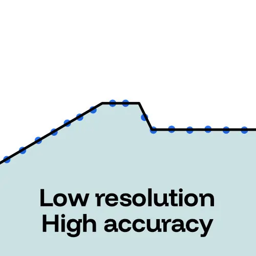
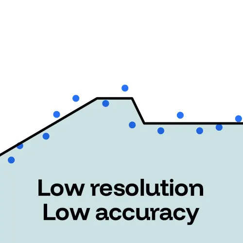
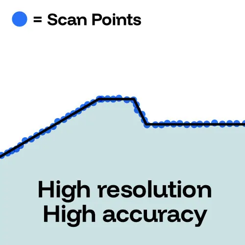
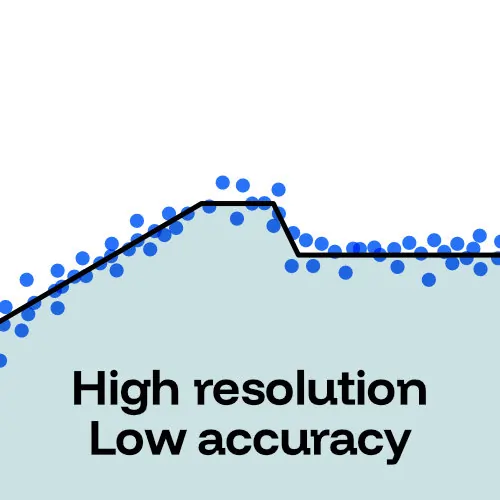
This defines how closely a measurement or point location matches real life. Single scan accuracy refers to the precision between two points within the same frame, while volumetric accuracy describes the reduction in accuracy as the scanned area increases and the scanner moves further from its starting point. There are, however, techniques to minimise this drop-off.

Resolution

The resolution determines the level of detail or sharpness in a scan. For example, if a part contains features of 0.1 mm, a scan resolution of 0.2 mm will not capture them. Resolution refers to the number of points recorded within a given area and the spacing between those points.

3.0 Handheld vs. Fixed Scanners​

Both types of scanner offer their own advantages and limitations.

Mobile scanners are far more versatile, capable of accessing confined spaces, reaching remote locations, and handling a wider range of part sizes. However, they often rely on scan targets to achieve the same level of accuracy and resolution as their fixed-arm counterparts, which typically offer greater stability and precision over longer ranges.

4.0 Datum Features & Alignments​

When scanning for inspection, validation, or comparison with CAD data, please let us know if there are any specific surfaces or features you would like us to use as datums for alignment.
We use two primary alignment methods: Best Fit and Datum Feature.

Best Fit Alignment

This is the quickest and simplest method of aligning scan data to CAD data. It uses an averaged best fit of the geometry, aligning the scan data to the greatest number of points across the part. However, as this approach considers the entire part, it does not account for specific datum features such as flat faces, mounting points, or clip features, nor does it reflect the original design intent.

Datum Feature Alignment

This method aligns corresponding features—identified on the 2D drawing—between the scanned data and the CAD model. Using GD&T principles, our software then aligns the two datasets to ensure the inspection is accurate, consistent, and reliable.

5.0 Post Processing & Scan Development​​

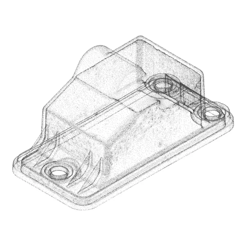
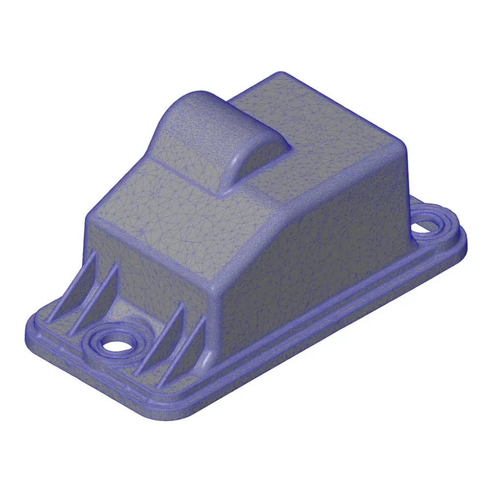
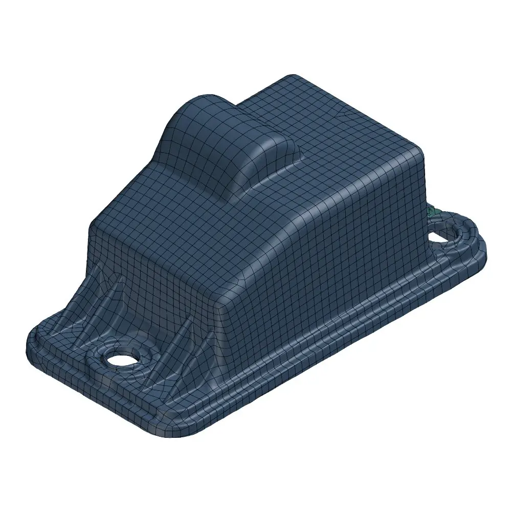
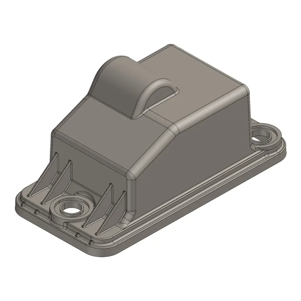
Once the scan is complete, post-processing may be required. Common reasons for this include multi-scan alignment, XYZ part alignment, hole filling, imperfection removal, file size reduction, and general mesh clean-up. Additionally, depending on the project, surface or feature creation may be carried out at this stage to produce a solid model for further use.
Point Cloud
Mesh
Reference Model
CAD Model

5.0 Part Preparation​​

Ensure the part is thoroughly cleaned and free from oil, dirt, and grease. Our scanners are highly precise and can detect even minor surface contaminants, such as paint thickness or residual grime. Vapour blasting automotive or motorcycle components prior to scanning provides an effective, non-aggressive cleaning solution. We can arrange this service through our trusted network of support partners if required.

6.0 Line of Sight

All 3D scanners operate using a combination of a camera sensor and a light source. As a result, they can only capture surfaces that are visible to them and accurately reproduce those areas digitally. This can make holes, pockets, and slots particularly challenging to scan.

As a general guideline, scanning deeper than one times the hole diameter will not yield reliable data. For instance, a scanner can typically ‘see’ only around 10 mm into a 10 mm diameter hole. When dealing with smaller holes, we recommend inserting a pin or dowel of the correct diameter to improve the accuracy and reliability of the captured data.